

Plug-in in terms of its substance, is generated by 2 some, namely plug-in, and connector, usually the condition is able to completely separate, switch and plug-in similarity lies in the change of the touch condition through its touch pairs, the implementation of the conversion of its connected circuit objectives, and the essence of the difference is that the plug-in only insert eradication of two types of conditions, the switch can be implemented in its own body circuit conversion, while the plug-in is not enough to implement the conversion in the The conversion of the body, the touch of the plug to the existence of a fixed corresponding link.
Some of the technical indicators of connectors are similar to those of switches, such as contact resistance, insulation resistance, voltage resistance, torque and life. The life of the connector is usually much lower than the switch, but its touch reliability should be much higher than the switch.
Selection of electrical connectors
Connectors are electromechanical components that connect electrical circuits. Therefore, the electrical properties of the connector itself is the first issue to refer to the selection of the connector. The accurate selection and application of electrical connectors is a primary aspect of ensuring the reliability of the circuit.
Introduction
Electrical connectors (hereinafter referred to as connectors) can also be referred to as plug holders, a comprehensive use of various types of electrical circuits, playing a role in connecting or disconnecting the circuit. Improving the reliability of the connector is first and foremost the responsibility of the manufacturer. But because of the variety of connectors, the use of a comprehensive range, therefore, the accurate selection of connectors is also a primary aspect of enhancing the reliability of the connector. Only through the producer and the application of the two sides together actively, in order to maximize the performance of the connector should be limited.
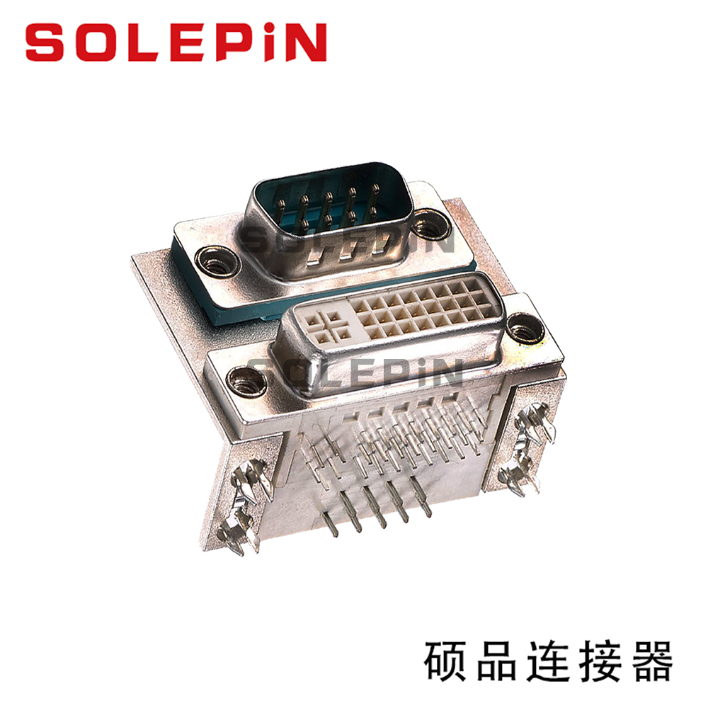
Connectors have different ways of classification. According to frequency, there are high-frequency connectors and low-frequency connectors; according to the shape of a circular connector, rectangular connectors; according to the use of points, there are printed circuit board connectors, cabinet connectors, audio facilities with connectors, power connectors, special connectors and so on. The following is the primary description of the selection of low-frequency connectors (frequency of 3MHZ below).
Electrical properties need
Connector is an electromechanical component that connects electrical routes. Therefore, the electrical properties of the connector itself is the first reference to the selection of the connector.
Rated voltage
Rated voltage, also known as operating voltage, it depends primarily on the insulation material applied to even the machinery, touching the size of the spacing between pairs. A certain type of component or device in the lower than its rated voltage, may not be able to complete its proper performance. Connector voltage rating should in fact be interpreted as the maximum operating voltage recommended by the manufacturer. Guidelines say that the connector in the lower than the rated voltage can work normally. The author prefers based on the connector's voltage (electrical strength) indicators, according to the application scenario, the need for safety grade to reasonably choose the rated voltage. That is, similar withstand voltage indicators, according to different application scenarios and safety needs, can be applied to different maximum operating voltage. This is also more suitable for subjective application conditions.

Rated current
Rated current is also known as operating current. The same as the rated voltage, in the lower than rated current conditions, connectors are usually able to work normally. In the connector design process, is through the thermal design of the connector to meet the rated current needs, because in the contact pair there is current flow period, because there is conductor resistance and contact resistance, the contact pair will be feverish. When the fever exceeds the absolute limit, it will destroy the insulation of the connector and generate the softening of the contact surface coating, resulting in failure. Therefore, to limit the rated current, in fact, to limit the temperature rise inside the connector does not exceed the design of the delineated value. In the selection of the issue to focus on is: for multi-conductor connectors, the rated current must be applied at a reduced rate. This should trigger more attention in the place of large currents, such as φ3.5mm touch on the, usually the rated current of 50A, and in 5 cores to derate 33% of the application, that is, the rated current of each core only 38A, the more cores, the greater the derating range. Derating range can refer to Table 1
Touch resistance
Touch resistance is the resistance of two touch conductors in touching some composition. In the selection of two issues to focus on, first, the connector touch resistance indicator is in fact touch resistance, which covers the touch resistance and touch on the conductor resistance. Often the conductor resistance is small, and thus the touch-to-resistance is called touch resistance in many skill standards. Second, in the circuit connected to the small signal, pay attention to the given touch resistance indicator is under what premise test, because the touch surface will be attached to the oxide layer, oil or other contaminants, the two touch parts will constitute a film layer resistance. When the thickness of the film layer increases, the resistance increases rapidly, and the film layer becomes a bad conductor. However, the film layer will produce machine breakdown under high contact pressure, or electrical breakdown under high voltage and high current. For a certain type of small volume connector design touch pressure is quite small, the application site is only mA and mV level, the film layer resistance is not easy to be breakdown, may be involved in the transmission of electrical signals. In GB5095 "electric in the facility with electromechanical components fundamental experimental procedures and measurement methods" in the touch resistance test one of the "touch resistance - millivolt punishment" delineated, in order to prevent the touch on the insulating film is broken, the test circuit of the open-circuit electric potential In fact, this is a class of low-level touch resistance test method, therefore, there is a need for the selector, due to the use of low-level touch resistance indicators of the connector.
Shielding
In the contemporary electrical and electronic facilities, the density of the elements and the gradual increase in performance between them, the electromagnetic disturbance put forward a strict limit. Therefore, the connector is usually enclosed with a metal shell to stop the internal electromagnetic energy radiation or by the external electromagnetic field annoyance. At low frequencies, the only magnetic material can be significant shielding effect on the magnetic field. At this point, there is an absolute delineation of the electrical continuity of the metal shell, which is the shell touch resistance.
Safety properties
Insulation resistance
Insulation resistance refers to the voltage applied to the insulation of a connector, which in turn causes the insulation to be
The insulation resistance is the resistance value that is shown by the leakage current in or on the surface of the insulation. It is mainly affected by the insulation material, heat, humidity, and dirt. Connector samples supplied on the insulation resistance value is usually all in the standard atmospheric premise of the indicator value, in a certain type of scenario premise, the insulation resistance value will not have to level of decline. In addition to focus on the insulation resistance of the experimental voltage value. According to the insulation resistance (MΩ) = the voltage (V) added to the insulator / leakage current (μA) to different voltages, there is no need for the results. In the connector experiment, the voltage is usually 10V, 100V, 500V three grades.
Withstand voltage
Withstand voltage is the touch pair of mutual insulation between some or insulation between some and ground, in a specified period of time can withstand higher than the rated voltage without constituting a breakdown of the critical voltage. It is mainly affected by the touch pair spacing and creepage distance and geometric shape, insulator material and scene heat and humidity, atmospheric pressure implication.